Gaojia Optotech
Introduction to Human Visual Function
Human visual function can be simply divided into two parts: the eyeball and the brain.
The brain can learn to recognize the external environment and objects through image learning, which is equivalent to the function of an artificial intelligence processor.
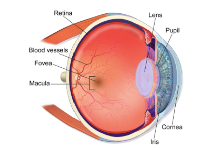
The eyeball is responsible for capturing images (equivalent to frame-based image sensors in cameras) and perceiving external changes (equivalent to event-based vision sensors). Please refer to the anatomical diagram of the human eye below:
There are two distinct types of photoreceptors in the human eye. The quantity and distribution of neurons are as follows:
• Cone cells (6 to 8 million, mainly located in the fovea centralis), responsible for capturing sharp color images.
• Rod cells (75 million to 150 million, distributed throughout the retina), function to perceive changes in external scenes.
In terms of the human eye's visual function of capturing sharp color images, the central part of the eyeball (fovea centralis) has a maximum resolution of approximately 8 million pixels. For the human eye's event detection capability, the entire retina delivers a maximum resolution of around 150 million pixels.
• The cornea and lens of the eyeball act as optical lenses.
• The iris and pupil are equivalent to the aperture of a lens.
• The fovea centralis (located at the center of the retina) is equivalent to an image sensor that receives sharp color images.
• The retina is used to rapidly detect pulsed events such as brightness changes, functioning as an event-based vision sensor.
When the retina perceives an event, the human brain sends commands to rotate the eyeballs or neck, aligning the center of the eye with the target of the event. This allows a clear image to form on the fovea centralis and be transmitted to the brain.
The seamless collaboration of four components — the fovea centralis, retina, eyeball, and neck rotation — enables visual neurons to perform complete visual functions in the most efficient manner, consuming fewer neurons and less optic nerve energy. Human evolution over millions of years is truly rational and ingenious.
Working Principle of a Camera
The working principle and components of a digital camera can be summarized by the following formula.
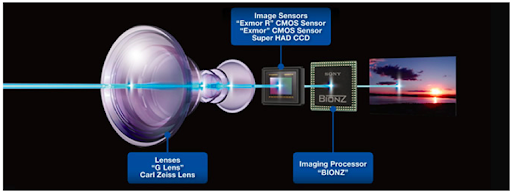
Camera = Lens + Image Sensor + Image Processor
Lens

(The image on the left is taken without a lens installed; the image on the right is taken with a lens installed.)
In addition to providing the basic focusing function, the lens can also add corresponding functions according to different requirements.
• Optical Zoom: Zooming in or out via optical zoom avoids image quality distortion.
• Field of View (FOV): Use wide-angle lenses (such as fisheye lenses) to change the camera's field of view.
• OIS (Optical Image Stabilization): Used to reduce image blur caused by hand shake during photography.
• DOF (Depth of Field): Adjust the lens aperture (F-number) to create different depth-of-field effects.
• Infrared Cut Filter: To capture photos with colors consistent with what the human eye perceives, infrared light needs to be filtered out, allowing only visible light (wavelengths from 400 nm to 700 nm) to reach the image sensor.
The demand for thinner and lighter smartphones limits the complexity and versatility of applicable lenses. However, smartphones can achieve various photographic effects—such as zooming, different fields of view, shallow depth of field (background blurring), and image stabilization—by adopting multiple lens-and-sensor combinations with different specifications, together with backend image processing technology.
Image Sensor
Image sensors can be regarded as a type of digital film. They are two-dimensional pixel arrays composed of countless photodiodes, designed to receive light transmitted through the lens. Each photodiode corresponds to one pixel in the image. A photodiode generates a corresponding digital signal intensity based on the number of photons it receives. The quantity of photons is determined by light intensity and exposure time. In other words, each photodiode outputs the brightness value of an individual pixel, and the entire pixel array forms the final image output by the image sensor. The following three sections will introduce the color format, resolution, and exposure control of image sensors.
Sensor Color Output Format
To produce color output, a Color Filter Array (CFA) is overlaid on the pixel array of the image sensor. The most dominant format of the color filter array is the Bayer pattern, as shown in the figure below.
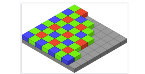
The CFA consists of the three primary colors blue, green and red arranged in a 2×2 BGGR adjacent pattern. In this configuration, each photodiode only receives light of one of the three colors: blue, green or red. Consequently, the image output by the sensor presents a mosaic pattern corresponding to the CFA layout, as illustrated in the figure.
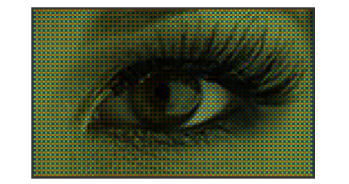
The Bayer image displays the converted signal intensity (i.e., brightness level) of each photodiode according to the number of red, blue, or green photons it receives. This raw image output by the sensor is known as a raw Bayer image. It requires further image processing to produce a viewable image for the human eye.
Image Sensor Resolution
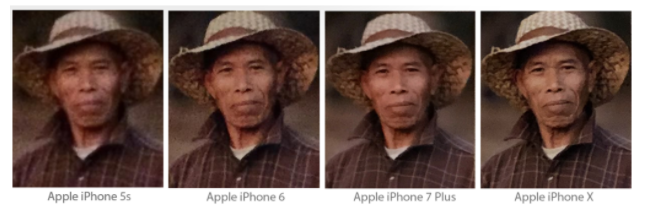
In the early 21st century, the image sensors used in the first-generation camera phones featured VGA resolution (640×480). Today, the resolution has reached 200 million pixels (16384×12288). In less than 20 years, the resolution of smartphone image sensors has increased by more than 650 times.
Photodiodes generate corresponding digital signal intensity according to the number of photons they receive. With the same exposure time, a larger photodiode can capture more photons than a smaller one. In other words, the larger the area of a photodiode, the better it can maintain image clarity in low-light environments.
When the overall size of an image sensor — calculated as the number of photodiodes multiplied by the area of a single photodiode — is limited by the size of smartphone lenses, increasing resolution by adding more photodiodes inevitably reduces the area of each individual photodiode. This means blindly boosting resolution compromises image fidelity, especially under low-light conditions. Achieving both high resolution and superior image quality simultaneously remains a key challenge to be addressed.
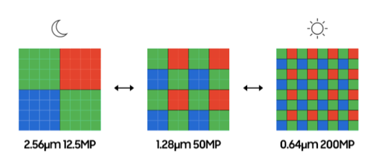
To balance high-resolution image performance and sharp imaging under medium and low brightness conditions, the figure below illustrates how Samsung maintains image clarity in dim environments by merging adjacent pixels in 2×2 or 4×4 binning modes.
200 million pixels appears to be an ideal resolution balance point. It not only delivers the digital zoom advantage of high resolution for outdoor daytime shooting, but also achieves excellent low-light photography through 2×2 or 4×4 pixel binning. Meanwhile, it supports output of 8K video (7680×4320) and 4K video (3840×2160).
Shutter Control of Image Sensor
Image sensors feature built-in shutter control, requiring no extra space like the mechanical shutters of traditional film cameras. Generally, shutter control for image sensors falls into two modes: global shutter and rolling shutter.
A global shutter means all pixels (photodiodes) start and end exposure at exactly the same time.
Rolling shutter, as the name suggests, operates in a scanning process similar to the raster scanning of a display. The exposure of the first row starts one row period earlier than that of the second row, and its exposure also ends one row period earlier. As a result, the exposure time window shifts downward row by row.
Each pixel has the same exposure duration, yet different rows carry different timestamps. This mode is relatively low-cost and delivers a higher frame rate, making it widely adopted in smartphone cameras. However, rapid movement of the subject or the camera itself can cause image blur and distortion.
Therefore, machine vision applications that cannot afford misjudgment caused by blurred images tend to prefer global shutter image sensors. A typical example is the TrueDepth camera in iPhone used for facial recognition.
Image Processor
The raw Bayer image output by the image sensor requires a series of complex image processing procedures before it can be rendered into a viewable image on the screen for the human eye. It is then compressed into JPEG photo files or H.264/H.265 video files.
The image processor is the component responsible for such image processing workflows. It also has an industry term: ISP (Image Signal Processor). This component consists of both hardware and software. The following three sections will introduce the core internal functions of the ISP.
Lens Correction, Color Interpolation, Noise Reduction
Lens Correction
To enable the image processor to generate images consistent with what the human eye perceives, it must first compensate for the inherent limitations of the lens and image sensor. In particular, smartphone lenses with a low aperture value cause the corners of the image sensor to receive less light than the center, resulting in darker corners in the frame, as shown in the figure below.

The lens correction function of the image processor (ISP) adjusts the signal intensity of each image pixel according to its position in the frame, so as to eliminate lens vignetting. This function is clearly illustrated in the figure below.

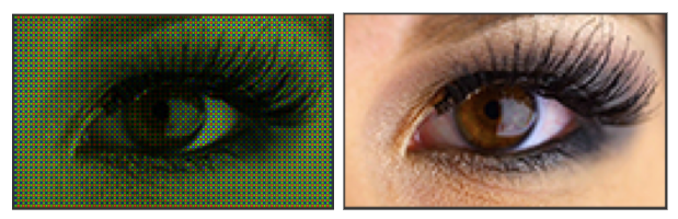
Color Interpolation
We have mentioned that the output of the image sensor adopts the Bayer pattern format. Since each pixel only outputs one of the three primary colors—red, blue, and green—the resulting image appears mosaic-like. One of the core functions of the Image Signal Processor (ISP) is color interpolation, also known professionally as demosaicing. This process enables every pixel to contain red, blue, and green color components, as shown in the figure.
Noise Reduction
The signal intensity of the image output by the image sensor can be described by the following formula:
Image signal intensity ∝ Ambient light intensity × Exposure time × Sensor pixel area
As mentioned earlier, the pixel (photodiode) area of an image sensor is proportional to the number of photons it captures. When ambient light is dim and sensor pixel size is small, the image output by the sensor will contain more noise under a fixed exposure time limit. This explains why smartphone cameras, which use tiny sensor pixels, require their Image Signal Processors (ISP) to continuously evolve more advanced noise reduction technologies.
Auto Exposure / Auto White Balance / Auto Focus
The camera Image Signal Processor (ISP) features the so-called 3A software control functions: Auto Exposure (AE), Auto White Balance (AWB) and Auto Focus (AF).
• AE Auto Exposure ControlCameras generally have a target average brightness for the overall output image. AE calculates the average brightness of the image output from the sensor in real time. If the measured brightness is lower than the target value, the AE algorithm increases the sensor’s exposure time; if it is higher than the target, AE reduces the exposure time. This adjustment continues until the average brightness of the sensor output matches the expected level.
AWB — What is Camera Auto White Balance?
When our eyes look at a white or gray object, it means the object reflects red, green and blue light with equal intensity.
When the image sensor receives the reflected light from a white or gray object, even if the incident RGB light intensity is identical, the object in the image output by the sensor will not appear white or gray.
This is because the photon-to-charge conversion rate of the sensor’s photodiodes varies with wavelength, namely color.
Camera Auto White Balance (AWB) adjusts the red gain and blue gain according to the efficiency distribution of the sensor in converting photons of different wavelengths into electric charges, so that the color of the image output by the sensor is consistent with what the human eye perceives.
• Auto Focus (AF) can be divided into passive autofocus and active autofocus.
Passive autofocus uses image contrast detection to locate the lens position corresponding to the sharpest edges in the frame.Active autofocus directly adjusts the lens position by measuring the distance between the camera and the subject.
In general, cameras adopt both methods simultaneously, known as hybrid autofocus: it first applies active autofocus for rough focusing, then performs contrast detection for fine tuning.
Since smartphone cameras must meet the requirements of light weight and slim design, the phase detection sensors for active autofocus are ingeniously integrated into the sensor pixels. Each pixel is divided into a left half and a right half, forming the so-called dual pixel. Both halves of the pixel receive incident light. The phase difference information obtained from the two parts is used to adjust the lens position, achieving fast autofocus.
However, if the subject lacks feature variations in the horizontal direction, the left-right split dual pixels cannot achieve accurate focusing. For this reason, the latest sensors have adopted vertically split pixel designs, as shown in the figure below.
In addition, since the divided pixel areas become smaller, the phase difference acquired in extremely low-light conditions is susceptible to noise interference. For this reason, high-end smartphone cameras are equipped with Laser AF to measure distance, assisting autofocus performance for night photography scenarios.
Possible Future Development Directions of Smart Cameras
Current smart cameras adopt frame-based cameras, such as smartphone cameras. Limited by the computing power of existing AI processors, images are usually scaled down to VGA resolution or lower in both height and width before the AI processor can start object recognition computation. This greatly constrains and limits the application scenarios of smart cameras, due to the low input image resolution and relatively long image transmission latency.
At present, the industry is also developing event-based visual sensors that mimic the functions of the human retina. Figure 14 illustrates the differences between such sensors and traditional frame-based image sensors. So far, event-based sensor technology is not as mature as frame-based image sensors. Meanwhile, even frame-based image sensors still have room for continuous improvement in performance such as High Dynamic Range (HDR) and Signal-to-Noise Ratio (SNR).
If we can mimic the division of labor between the human fovea and retina—that is, using a high-resolution color frame-based image sensor to perform the function of the human fovea, and another event-based visual sensor to perform the function of the retina. When the event sensor detects an event, the frame-based image sensor will output one or more image frame regions (i.e., ROI—Region of Interest) using the event coordinates detected by the event sensor.
These different ROIs can have different exposure parameters, thereby enabling each ROI to achieve optimal image quality. Afterwards, the AI processor only needs to recognize these ROIs, instead of processing the entire scaled-down frame output by the frame-based sensor.
This process not only provides low-latency, higher-resolution ROI images, but also significantly reduces the power consumption of the high-resolution frame-based sensor and the AI processor. This will enable smart cameras to achieve visual recognition effects close to those of the human eye in various environments.